
close
Choose Your Site
Global
Social Media


Views: 0 Author: Site Editor Publish Time: 2026-07-29 Origin: Site


A short-circuit event creates an extreme physical reality inside a power transformer. When a fault occurs, peak currents generate massive electromagnetic forces that can destroy the internal geometry of the unit in milliseconds. Mechanical failure presents a catastrophic operational and financial risk to any power grid or industrial facility. Electrical protection systems, such as relays and circuit breakers, are necessary to clear the fault. However, the physical survival of the asset relies entirely on the mechanical rigidity of its internal structure before that circuit clears. The transformer clamp acts as the primary mechanical defense mechanism against these destructive forces. Evaluating the engineering, material science, and standard compliance of clamping systems is a mandatory step. Procurement and engineering teams must assess these factors to guarantee transformer reliability and prevent catastrophic failure during grid disturbances.
Mechanical Rigidity is Non-Negotiable: A transformer clamp must absorb and distribute both axial and radial dynamic forces to prevent winding displacement and insulation rupture.
Material and Design Synergy: Effective transformer core clamping parts balance high tensile strength with non-magnetic properties to prevent localized overheating and structural fatigue.
Pre-Compression is Critical: Maintaining continuous clamping pressure over the transformer's lifespan is required to counteract the natural settling and shrinkage of winding insulation.
Standardized Verification: Compliance with IEC 60076-5 and IEEE standards provides the baseline empirical proof of a design’s short-circuit withstand capability.
Engineers define the baseline physical challenge through strict success criteria. The success of any clamping system is measured by a specific metric. It must maintain zero critical displacement under peak asymmetrical fault currents. Any movement compromises the dielectric integrity of the insulation system. We measure this success by inspecting the unit after a fault to ensure the windings have not shifted, telescoped, or deformed.
Short-circuit currents generate two distinct types of destructive mechanical stress. Radial forces push inner windings inward toward the steel core. Simultaneously, they push outer windings outward away from the core. This outward expansion creates severe hoop stress on the conductors, stretching the copper or aluminum beyond its yield point if unsupported. Axial forces act vertically along the length of the winding cylinder. They compress or telescope the windings vertically, driving them up into the upper yoke or down into the lower frame.
These forces compound simultaneously during the first few cycles of a fault. The resulting dynamic load acts like a massive hydraulic press striking the internal components. Field inspections of failed units often reveal outer windings that look like birdcages, a direct result of unmitigated radial expansion. Axial failures present as crushed spacer blocks and torn paper insulation. The clamping structure must resist both vectors of force simultaneously.
Force Type | Direction of Action | Primary Component Affected | Failure Mechanism if Unclamped |
|---|---|---|---|
Radial (Inner) | Inward toward the core | Inner Low Voltage Winding | Buckling of the winding cylinder against the core steel. |
Radial (Outer) | Outward away from the core | Outer High Voltage Winding | Conductor stretching, hoop stress failure, "birdcaging". |
Axial (Compression) | Vertical compression | Winding Discs and Spacers | Crushing of radial spacers, damage to turn-to-turn insulation. |
Axial (Expansion) | Vertical telescoping | Entire Winding Assembly | Windings driving into the yoke, catastrophic dielectric failure. |
Every clamping structure has an exact mechanical threshold. Dynamic short-circuit forces can sometimes exceed the designed clamping force. When this threshold is crossed, the physical consequences are immediate and severe. Instantaneous vertical displacement occurs. Conductor tilting follows rapidly. Finally, the irreversible buckling of winding layers destroys the transformer. The clamping system must maintain a pre-compression force greater than the maximum calculated axial fault force.
We calculate this tipping point using finite element analysis during the design phase. If the pre-compression is 500 kN, but the fault generates 600 kN of upward axial force, the windings will lift. Even a movement of a few millimeters can tear the paper insulation wrapped around the conductors. Once the insulation tears, a turn-to-turn short develops, leading to an internal arc and rapid gas generation.
Transformer impedance shares an inverse relationship with short-circuit current magnitude. Higher impedance limits the peak fault current. Lower impedance allows massive currents to flow during a fault. Variations in impedance directly impact the mechanical load calculations required for the clamping structure. For instance, a ± 10% variation in auto-transformers significantly alters the maximum fault current.
Engineers must design the clamping system to handle the absolute worst-case scenario based on minimum possible impedance values. If a transformer has a nameplate impedance of 8%, the mechanical design might assume 7.2% to account for manufacturing tolerances. This conservative approach ensures the clamping structure can handle the highest possible fault current the network can deliver.
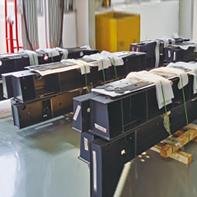
Manufacturers utilize specific mechanical approaches to secure the core and windings against dynamic loads. These solution categories form the backbone of transformer mechanical design. A robust transformer core clamp integrates multiple components to create a rigid cage around the active part.
Axial clamping mechanics are fundamental to transformer survival. The clamping system applies continuous downward pressure on the windings. This pressure counteracts the upward and downward thrust generated by axial short-circuit forces. If the clamping pressure is inadequate, the windings will move. This movement leads to insulation tearing. Turn-to-turn faults quickly follow, resulting in complete dielectric failure.
To establish this pressure, assembly technicians follow a strict sequence:
Lower the winding assemblies onto the bottom clamping frame and insulation blocks.
Install the top yoke steel, carefully interleaving the laminations.
Position the upper clamping frame over the yoke.
Install the vertical tie rods connecting the top and bottom frames.
Torque the jack bolts on the upper frame to apply the specified pre-compression force to the pressure rings.
Measure the winding height to verify the correct compression has been achieved.
The anatomy of the clamping system involves several interconnected components. Flitch plates run vertically along the core limbs. Tie rods connect the upper and lower clamping frames. Pressure rings distribute force evenly across the winding circumference. Jack bolts apply the final compression force. These components work as a unified mechanical framework.
They transfer stress away from fragile copper or aluminum windings. The stress is channeled directly into the robust steel core structure. High-quality transformer core clamping parts ensure this load transfer occurs without component deformation. If a pressure ring flexes under load, the force distribution becomes uneven, leading to localized winding damage.
Engineers must assess competing transformer designs through specific technical lenses. Evaluating the mechanical structure requires a deep understanding of materials and assembly techniques. You cannot rely solely on electrical specifications when procuring a transformer for a high-fault environment.
Material selection involves significant trade-offs. The clamping structure requires immense tensile strength. Structural steel provides this strength but is highly magnetic. Non-magnetic stainless steel or specialized composites offer lower magnetic permeability. High magnetic permeability increases the risk of stray flux heating in clamping components. Excessive heating degrades nearby insulation.
Engineers must choose materials that mitigate thermal degradation while maintaining structural rigidity. Flitch plates are often made of non-magnetic stainless steel to prevent them from acting as a shorted turn and overheating. Pressure rings are typically manufactured from high-density laminated wood or specialized polymers to provide electrical isolation while transferring mechanical load.
Material | Typical Application | Tensile Strength | Magnetic Permeability |
|---|---|---|---|
Carbon Steel | Main upper and lower frames | High | High (Requires shielding) |
Stainless Steel (304/316) | Flitch plates, tie rods near high flux | Medium-High | Low (Non-magnetic) |
Laminated Wood | Pressure rings, support blocks | Medium | Zero (Insulator) |
Glass-Reinforced Polymer | Specialized pressure rings, spacers | High | Zero (Insulator) |
Pre-compressing windings during manufacturing is an absolute necessity. Manufacturers use various mechanisms to maintain this pressure over decades of operation. Belleville springs provide dynamic tension. Hydraulic clamping ensures precise force application during assembly. Epoxy-bonded continuous transposed cables add inherent structural rigidity to the windings themselves.
Sustained pre-compression prevents the hammer effect. This effect occurs when loose windings slam against the clamping plates during a short circuit. If the windings are allowed to accelerate before hitting the clamping structure, the impact force multiplies, easily shattering laminated wood pressure rings and bending steel frames.
Clamping demands vary significantly between general-purpose dry-type transformers and liquid-immersed units. Dry-type units utilize specialized resin-encapsulated support blocks. They rely on surface clamps optimized for air cooling and thermal expansion. Oil-filled designs require heavy-duty steel clamping parts. They utilize adjustable jack screws immersed in insulating oil to maintain pressure.
Dry-type transformers often use fiberglass tie rods to maintain compression without introducing conductive materials into the air gaps. Liquid-immersed units leverage the dielectric strength of the oil, allowing for massive steel structures closer to the active parts, provided they are properly insulated and shielded from stray flux.
The interface between metal clamping parts and winding insulation requires careful design. Common insulation materials include pressboard, laminated wood, or high-density polymers. Clamping structures must accommodate thermal expansion and contraction. Transformers undergo continuous thermal cycling during normal load variations.
The clamping system must maintain mechanical tightness without crushing the insulation during high-temperature operation. When the transformer is fully loaded, the copper expands. The clamping system must absorb this expansion. When the load drops and the unit cools, the system must spring back to maintain pressure on the shrinking windings.
Industry-standard frameworks validate claims of mechanical resilience. These standards ensure that theoretical designs hold up in real-world fault conditions. Relying on calculations alone is risky; empirical testing provides definitive proof of a design's capability.
Physical testing procedures are strictly dictated by IEC 60076-5. There is a major difference between calculated withstand capability and empirical testing. Design reviews rely on mathematical models and finite element analysis. Empirical testing involves destructive or non-destructive lab tests. During these tests, the transformer is subjected to actual short-circuit currents.
The test facility connects the transformer to a massive power source, often a dedicated short-circuit generator. They apply the fault for a specified duration, usually 0.25 to 0.5 seconds. The forces generated during this test replicate the worst-case scenario the transformer will face in the field.
Post-test diagnostic methods verify clamp integrity. Sweep Frequency Response Analysis (SFRA) detects minute shifts in winding geometry. Leakage reactance measurements identify bulk deformation. A pass requires zero significant structural deformation. The transformer must maintain its original dielectric clearances and pass all routine electrical tests after the short-circuit event.
Field technicians use the following diagnostic sequence after a suspected fault:
Perform a visual inspection of the external tank for bulging or deformation.
Draw an oil sample for Dissolved Gas Analysis (DGA) to check for arcing or overheating.
Conduct Leakage Reactance testing to check for bulk winding movement.
Run an SFRA test and compare the traces to the factory baseline.
If SFRA indicates movement, open the inspection covers and visually check the jack bolts and pressure rings.
Real-world manufacturing and operational variables can compromise an otherwise sound design. Addressing these implementation risks ensures long-term reliability. Even the best engineering calculations fail if the factory assembly is flawed.
Insulation shrinkage over time is a major risk. Moisture extraction and thermal aging cause pressboard to compress. This leads to a loose clamping structure. Mitigation strategies include specifying designs with self-adjusting clamping mechanisms. Strict factory drying protocols are also essential.
Vapor Phase Drying (VPD) removes moisture completely before final clamping, minimizing future shrinkage. The active part is heated under vacuum, extracting water from the cellulose insulation. Once dry, the assembly is immediately re-clamped to account for the shrinkage that occurred during the drying process.
Commercial trade-offs exist in mechanical design. Over-engineering the clamping structure increases weight and footprint. It also drives up upfront capital expenditure. Engineers must balance these costs against the criticality of the installation. Generator step-up transformers require maximum rigidity due to high fault current potential.
Standard distribution units may utilize more standardized, cost-effective clamping frameworks. You must evaluate the fault level at the specific installation site. A transformer installed near a large generation source requires a much more robust clamping system than one installed at the end of a long, high-impedance rural distribution line.
The mechanical design of the clamping system is the ultimate fail-safe against catastrophic short-circuit destruction. Procurement teams must demand detailed mechanical force calculations and material specifications for all clamping parts during vendor evaluation.
Request dynamic short-circuit withstand test reports from your transformer manufacturers before finalizing the purchase order.
Consult structural engineers to review the clamping mechanisms and finite element analysis of proposed transformer assets.
Verify material specifications for all core clamping components to ensure low magnetic permeability and adequate tensile strength.
Implement routine SFRA diagnostics during maintenance cycles to monitor clamping pressure and detect early signs of winding movement.
A: During a short circuit, the clamp faces the sudden application of extreme axial and radial dynamic forces. It resists massive mechanical stress to hold the windings in place. If designed correctly, it prevents structural deformation, ensuring the windings do not telescope or buckle under the peak asymmetrical fault current.
A: Engineers calculate clamping force using finite element analysis. They consider the peak asymmetrical fault current, winding geometry, and transformer impedance. The calculation determines the maximum axial and radial forces generated. The clamping system is then designed to apply a pre-compression force exceeding these calculated dynamic loads.
A: Manufacturers use high-tensile structural steel for main frames. They use non-magnetic stainless steel for components near high magnetic flux to prevent heating. Specialized insulating pressure rings made of laminated wood or high-density polymers interface directly with the windings. This balances mechanical strength with thermal management.
A: Mechanical destruction occurs in milliseconds. This happens often before relays and circuit breakers can physically interrupt the fault current. If the internal clamping structure lacks rigidity, the electromagnetic forces will instantly displace windings and tear insulation. Structural rigidity is essential to survive the fault until the breaker opens.
A: Radial forces act horizontally. They create hoop stresses that expand outer windings and compress inner windings toward the core. Axial forces act vertically. They push windings up or down, attempting to telescope the conductor layers. Both forces act simultaneously during a fault event.
A: IEC 60076-5 sets the minimum requirements for calculating and testing dynamic short-circuit withstand capability. It forces manufacturers to engineer robust clamping systems. The standard outlines specific testing procedures and diagnostic criteria to prove the mechanical framework can survive peak fault currents without deformation.
A: No. Dry-type systems rely on solid resin casting, fiberglass blocks, and surface-bound clamping parts optimized for air cooling. Liquid-immersed units use high-pressure structural steel plates, tie rods, and adjustable jack screws. These heavy-duty components are designed to operate while immersed in insulating oil.


