
close
Choose Your Site
Global
Social Media


Views: 0 Author: Site Editor Publish Time: 2026-07-28 Origin: Site


Magnetostriction in dry-type and oil-filled transformers is an unavoidable physical reality, but excessive acoustic noise and escalating core loss are indicators of structural failure, not inevitability. Improperly specified or deteriorating clamping structures allow core laminations to vibrate. This mechanical movement unevenly distributes flux density, increases audible noise beyond regulatory compliance, and accelerates mechanical degradation, ultimately reducing transformer efficiency and lifespan. To specify transformers that maintain long-term efficiency and acoustic compliance, engineering and procurement teams must evaluate the precise mechanics of clamping pressure, the materials used, and the structural design of the clamping system.
Optimal tension is a narrow threshold: Both under-tightening (allowing lamination vibration) and over-tightening (inducing mechanical stress and damaging insulation) negatively impact core loss.
Noise is a symptom of mechanical degradation: Escalating audible noise indicates core loosening, which directly correlates with increased magnetostriction and reduced operational efficiency.
Material selection dictates damping capacity: Integrating specific damping materials (like industrial rubber) within the transformer clamp assembly significantly alters the vibration profile and hysteresis losses.
Long-term reliability requires thermal consideration: Clamping structures must account for thermal cycling, which naturally causes expansion, contraction, and eventual loosening if not properly engineered.
The baseline requirement for a transformer core is straightforward. It must maintain a rigid, unified magnetic path under continuous alternating current without structural yielding. You need the core to act as a solid, monolithic block. This is difficult because manufacturers build cores from hundreds or thousands of individual thin silicon steel sheets. Achieving this unified state requires overcoming the inherent physical forces generated during electrical transformation.
Magnetostriction drives core vibration. As alternating magnetic fields pass through the core, the magnetic domains within the silicon steel align and realign with the alternating current. This continuous realignment causes the physical dimensions of the steel laminations to change microscopically. The dimensional change is minute. We often measure it in parts per million. However, the sheer volume of laminations and the continuous 50Hz or 60Hz frequency result in a massive aggregate mechanical force. If you do not hold the core rigidly, this force manifests as high-frequency vibration.
Internal mechanical stress within the core material also dictates performance. During the manufacturing process, cutting, slitting, and stacking the silicon steel introduces mechanical stress. This stress disrupts the optimal alignment of magnetic domains. Facilities use post-manufacturing annealing to relieve this stress and restore the material's magnetic properties. But if the assembled core faces uneven or excessive mechanical pressure later, new stresses emerge. These new stresses degrade the magnetic path.
The transformer clamp acts as the primary mechanical countermeasure against these forces. It applies uniform compressive force across the entire stacked assembly. This restricts lamination movement and maintains a stable, low-reluctance magnetic circuit. By physically binding the laminations together, the hardware prevents microscopic expansions from compounding into destructive macroscopic vibrations. Field engineers know that a well-designed clamping system is the only thing keeping a transformer from shaking itself apart over a twenty-year lifespan.
When we look at the actual construction on the shop floor, the stacking method matters. Step-lap joints reduce the air gap at the corners of the core. But step-lap joints are fragile. They require precise, uniform pressure to maintain their low-loss characteristics. If the clamping structure warps or applies uneven pressure, the step-lap joints separate. This separation immediately spikes the no-load losses. Therefore, the structural integrity of the frame is just as important as the grade of silicon steel used in the laminations.
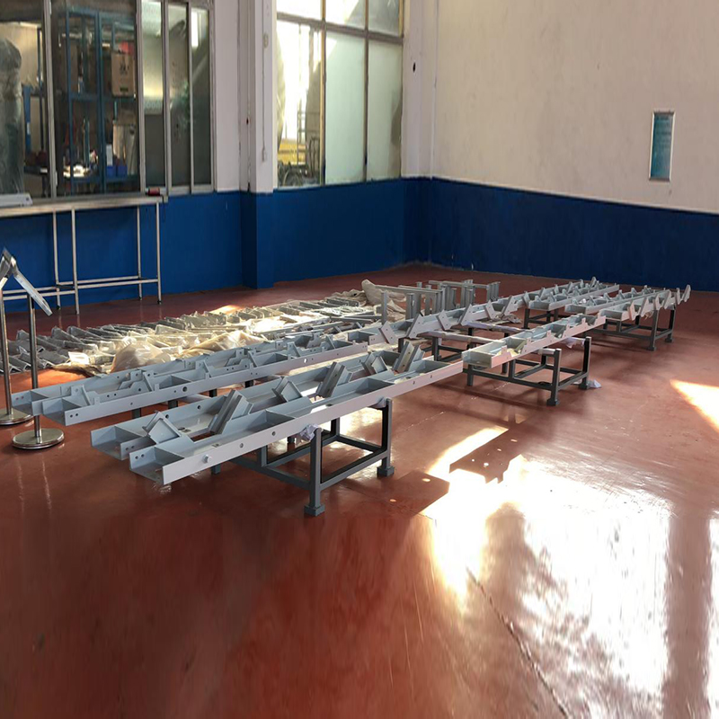
Clamping pressure maps directly to electrical efficiency and thermal output. The relationship between mechanical tension and core loss operates within a strict optimal window. Deviating from this window in either direction yields severe electrical penalties. You cannot simply tighten the bolts as much as possible and walk away.
Under-tightening creates microscopic air gaps between the individual silicon steel laminations. Magnetic flux naturally seeks the path of least resistance. When air gaps exist, the flux must jump across these high-reluctance spaces. This leads to uneven flux distribution. Localized areas of the core carry a disproportionate amount of the magnetic load, pushing them into magnetic saturation. Saturation exponentially increases hysteresis losses. It also spikes eddy current losses, which manifest as excessive heat. We see this in the field when thermal imaging reveals hot spots near the core yokes.
The risks of over-tightening are equally destructive. Excessive clamping force introduces two primary failure modes that ruin efficiency.
Destruction of inter-laminar insulation: Transformer laminations have a microscopic layer of carlite or similar insulating material. This prevents electrical conductivity between the plates. Over-tightening crushes this fragile coating. It creates electrical short circuits between adjacent laminations. Massive eddy currents then circulate through the core block, causing severe localized heating.
Reintroduction of internal stress: Pushing the compressive force beyond the material's tolerance reintroduces high internal mechanical stress into the annealed silicon steel. This stress physically restricts domain wall motion. The transformer requires more energy to magnetize the core, increasing overall core loss.
Experimental data highlights these performance disparities. In benchmark tests of 3-phase 100 kVA transformers, unclamped cores exhibit the highest losses. Standard rigid metal clamped cores show significant improvement. However, cores utilizing specialized rubber-damped clamping assemblies demonstrate the lowest core losses. The damping material absorbs the kinetic energy of the magnetostriction. It prevents the vibration from disrupting the magnetic flux path while maintaining uniform pressure without crushing the insulation.
Establishing the optimal tension window requires precise engineering frameworks. Manufacturers calculate the exact torque and pressure required based on the specific core size, lamination thickness, and kVA rating. This ensures the pressure closes air gaps but protects the insulation.
Clamping Condition | Mechanical State | Flux Distribution | Core Loss Impact |
|---|---|---|---|
Under-Tightened | Loose laminations, high vibration | Uneven, localized saturation | High hysteresis and eddy current losses |
Optimally Tightened | Rigid block, minimal vibration | Uniform, low reluctance | Baseline/Nameplate losses achieved |
Over-Tightened | Crushed insulation, high internal stress | Short-circuited laminations | Massive eddy current spikes, overheating |
Transformer noise is a strict compliance issue. Regulatory standards like NEMA TR 1 and IEC 60076-10 dictate the maximum allowable decibel levels for transformers installed in commercial, residential, and industrial environments. Failing to meet these acoustic standards requires expensive retrofits, sound enclosures, or complete unit replacement. You do not want to fail a sound test on a newly commissioned substation.
Mechanical resonance is the primary culprit behind excessive noise. When a core is loosely clamped, magnetostrictive vibrations amplify. This amplification is severe at the joints where the core yokes meet the core legs. If the frequency of this amplified vibration matches the natural resonance frequency of the transformer enclosure, the noise level spikes dramatically. It creates a loud, continuous hum that travels through concrete pads and building structures.
The progression of loose clamping follows a predictable failure sequence. It begins with microscopic core lamination vibration. Over time, this continuous movement causes clamp movement and displacement. As the clamp shifts, the pressure becomes uneven. This leads to uneven flux density distribution. The uneven flux exacerbates the magnetostriction in localized areas, resulting in high-decibel audible noise and accelerated mechanical wear.
Integrating damping technologies into the transformer core clamp is a highly effective mitigation strategy. Engineering studies utilizing Rayleigh damping parameters demonstrate that specialized damping materials significantly alter the acoustic profile. When placed between the steel clamping plates and the core laminations, industrial-grade nitrile rubber absorbs the high-frequency kinetic energy. This prevents the vibration from transferring through the rigid mounting hardware into the outer enclosure. It effectively decouples the acoustic source from the radiating surfaces.
If you are troubleshooting a noisy transformer in the field, follow these steps to identify clamping issues:
Perform a baseline acoustic sweep using a calibrated decibel meter at the NEMA-specified distances.
Use a mechanic's stethoscope or vibration analyzer on the external enclosure to locate the highest amplitude vibration points.
De-energize and isolate the transformer following standard safety protocols.
Inspect the internal core clamping hardware for visible signs of shifting, loose nuts, or degraded damping pads.
Verify the torque on all accessible tie-rods and yoke bolts against the manufacturer's original specifications.
Specifiers must critically evaluate the physical components of a transformer's structural design to ensure long-term reliability. The methodology used to secure the core dictates how well the unit will withstand decades of continuous operation. You cannot accept generic hardware for a critical infrastructure asset.
Core yoke and leg clamping mechanisms vary significantly across different designs. Through-bolts are a traditional method. They pass directly through holes punched in the laminations. While highly secure, punching holes disrupts the magnetic flux path and increases localized losses. External tie-rods bypass the laminations entirely. They apply pressure to external clamping plates. This preserves the magnetic path but requires highly rigid external frames. Epoxy-banded cores utilize high-strength, heat-cured resin bands to bind the legs. This offers excellent uniform pressure without metallic interference.
Material trade-offs play a major role in the selection of transformer core clamping parts. Each material presents distinct advantages and engineering challenges. We see a shift toward advanced composites in modern dry-type units, but heavy steel remains the standard for large oil-filled power transformers.
Material Type | Primary Advantages | Engineering Limitations | Common Applications |
|---|---|---|---|
Structural Steel | High rigidity, exceptional tensile strength, long-term durability. | Requires careful grounding and insulation to prevent eddy currents within the clamp itself. Susceptible to corrosion if unpainted. | Large power transformers, heavy industrial applications. |
Laminated Densified Wood | Excellent electrical insulation, completely non-magnetic, eliminates eddy currents in the clamp. | Susceptible to moisture absorption and thermal degradation over decades of use. Lower tensile strength than steel. | High-voltage applications, specialized distribution transformers. |
Composite / Fiberglass | High tensile strength, non-conductive, non-magnetic, highly resistant to thermal degradation. | Requires precise manufacturing to ensure uniform pressure distribution. | Modern dry-type transformers, compact high-efficiency units. |
When evaluating fiberglass or composite clamping structures, pay attention to the pultrusion process used by the manufacturer. The glass fibers must be oriented correctly to handle the continuous compressive load. If the composite matrix degrades under high operating temperatures, the core will loosen just as it would with stretched steel bolts.
Clamping effectiveness naturally degrades over time. Recognizing and mitigating these lifecycle risks during the specification and maintenance phases prevents catastrophic failure. A transformer that tests perfectly at the factory can become a noisy, inefficient liability five years later if the hardware cannot handle the operating environment.
Thermal cycling and mechanical fatigue are the primary drivers of core loosening. Transformers constantly heat up under heavy electrical load and cool down during off-peak hours. This continuous thermal cycling causes the metallic clamping materials, tie-rods, and core laminations to expand and contract at slightly different rates. Over thousands of cycles, this differential expansion leads to mechanical fatigue and a gradual loss of clamping tension. The steel bolts literally stretch over time.
Vibration-induced winding degradation is a severe secondary consequence of core loosening. The core and the electrical windings sit in close physical proximity. If the core vibrates excessively, this kinetic energy propagates directly into the windings. The continuous high-frequency vibration causes abrasive wear on the winding insulation. Over time, this friction wears through the dielectric barriers. It accelerates the risk of phase-to-phase or phase-to-ground short circuits. We often find evidence of this fretting wear during forensic teardowns of failed units.
Vibration-induced fastener back-out is another constant threat. The continuous 50Hz or 60Hz vibration acts as a mechanical loosening agent on standard nuts and bolts. Without proper securing mechanisms, the fasteners holding the clamping frame together will slowly back out. This leads to a sudden and rapid loss of core tension.
Effective mitigation strategies must be engineered into the transformer from the outset. Specifying Belleville washers on all clamping fasteners is non-negotiable for high-reliability units. These conical spring washers maintain constant mechanical tension even as the surrounding metals expand and contract during thermal cycling. Utilizing specialized locknuts or thread-locking compounds prevents vibration-induced back-out. Furthermore, establishing routine acoustic monitoring programs allows maintenance teams to detect the early acoustic signatures of core loosening long before it escalates into a destructive electrical fault.
The tightness and structural integrity of a transformer clamp dictate electrical efficiency, acoustic compliance, and asset longevity. A properly engineered clamping system prevents the destructive cycle of magnetostriction-induced vibration, localized overheating, and insulation failure. When evaluating transformer manufacturers, prioritize vendors who provide transparent data on their clamping methodologies, torque specifications, and damping material integration. A manufacturer's ability to articulate their approach to core tension is a direct indicator of their overall build quality.
Audit current transformer procurement specifications to ensure they include strict requirements for core clamping materials and tension maintenance.
Mandate the inclusion of thermal-cycling resilience hardware, such as Belleville washers, on all structural fasteners in future orders.
Implement baseline acoustic monitoring for all newly installed transformers to establish a reference point for future degradation analysis.
Request documented torque specifications and damping material data from vendors during the technical evaluation phase of equipment sourcing.
A: A loose clamp allows core laminations to vibrate excessively due to magnetostriction. This increases audible noise, creates uneven magnetic flux density, and raises core losses by forcing localized areas into magnetic saturation, generating excess heat and inefficiency.
A: Yes. Excessive clamping pressure can crush the thin insulating coating between the steel laminations, leading to short circuits between the plates, which drastically increases eddy current losses and localized heating. It also introduces mechanical stress that impairs magnetic performance.
A: Damping materials, such as specialized industrial rubber, absorb the mechanical kinetic energy generated by the vibrating core. This prevents the vibration from transferring to the outer enclosure and amplifying into audible noise.
A: Cores typically loosen due to thermal cycling (repeated expansion and contraction from heating and cooling) and continuous mechanical vibration, which can cause standard fasteners and tie-rods to gradually lose tension.
A: Common materials include structural steel (for high rigidity), densified wood (for non-magnetic, insulating properties), and fiberglass composites, often paired with spring washers to maintain tension.
A: Unchecked core vibration transfers directly to the adjacent windings. Over time, this mechanical movement degrades the physical insulation of the windings, leading to premature dielectric breakdown and electrical faults.
A: Transformer noise is measured in decibels (dB) and is regulated by industry standards such as NEMA TR 1 or IEC 60076-10, which dictate the maximum allowable sound levels based on the transformer's kVA rating and installation environment.


