
close
Choose Your Site
Global
Social Media


Views: 0 Author: Site Editor Publish Time: 2026-07-24 Origin: Site


Transformers operate as highly efficient static devices on the electrical grid. Continuous energization means that even marginal inefficiencies compound into massive operational energy drains over a 20- to 30-year lifecycle. Procurement and engineering teams face constant tension between minimizing initial capital expenditure and managing long-term operational efficiency. Substandard manufacturing directly inflates no-load losses, commonly known as iron losses. It also causes non-compliance with strict municipal noise ordinances, leading to site disputes and retrofit requirements.
Technical procurement teams must move beyond basic nameplate ratings. You must evaluate the specific metallurgical and manufacturing quality of the transformer core to guarantee long-term performance and regulatory compliance. Understanding the physical construction of the core allows you to specify equipment that delivers reliable, quiet, and efficient power distribution across your infrastructure.
Material Dictates Baseline Efficiency: The specific grade of a CRGO transformer core determines the fundamental limits of hysteresis loss and magnetostriction-induced noise.
Manufacturing Precision Multiplies Performance: Poor transformer lamination cutting, inadequate burr control, and improper stacking can degrade even the highest-grade steel, spiking eddy current losses.
Noise is a Diagnostic Tool: Excessive audible noise often indicates core saturation, poor clamping, or internal mechanical resonance, serving as a leading indicator of core degradation.
Lifecycle Cost Outweighs Upfront Costs: Rigorous Factory Acceptance Testing (FAT) for no-load loss and excitation current is critical to validating supplier claims and avoiding hidden lifecycle penalties.
No-load loss is the continuous energy penalty incurred simply by energizing the transformer. This loss happens regardless of the load demand on the system. Minimizing this baseline power draw is a primary success criterion for modern electrical infrastructure. When a transformer sits idle but energized, it still consumes power. This continuous draw requires generation capacity and fuel, making it a permanent drain on system efficiency.
We must differentiate no-load loss from load loss. No-load loss occurs continuously in the core due to excitation voltage. Load loss occurs in the windings under load due to current flow. Load loss is heavily influenced by winding conductor size and the facility's load profile. Core losses remain constant at a given operating voltage and frequency. This constant draw makes them a 24/7 financial drain on your power network. Engineers must account for both, but core loss represents the absolute baseline of inefficiency.
Alternating current forces the continuous realignment of magnetic domains within the core material. This realignment requires energy, which dissipates as heat. We call this hysteresis loss. The metallurgical purity, magnetic flux density, and grain orientation of the steel dictate the energy required for this realignment. High-grade steel requires less energy to flip these magnetic domains. Using inferior steel means the magnetic domains resist realignment, generating excess heat and wasting power every single cycle.
Alternating magnetic fields induce localized circulating currents within the core steel. These are eddy currents. To restrict these currents, manufacturers use ultra-thin transformer lamination sheets. Inter-laminar insulation coatings, such as Carlite, provide high electrical resistance between the sheets. Thinner laminations with robust coatings significantly reduce eddy current losses. If the insulation fails or the laminations are too thick, these circulating currents grow large enough to cause severe localized heating.
Excitation current is the current required to establish the magnetic flux in the core. It shares a direct relationship with core saturation and operating magnetic flux density. Poor core geometry, over-fluxing, or material degradation forces the system to draw higher excitation current. This higher draw maintains the required magnetic flux but reduces the overall system power factor. A high excitation current indicates that the core is struggling to maintain the magnetic field, often pointing to poor material quality or assembly defects.
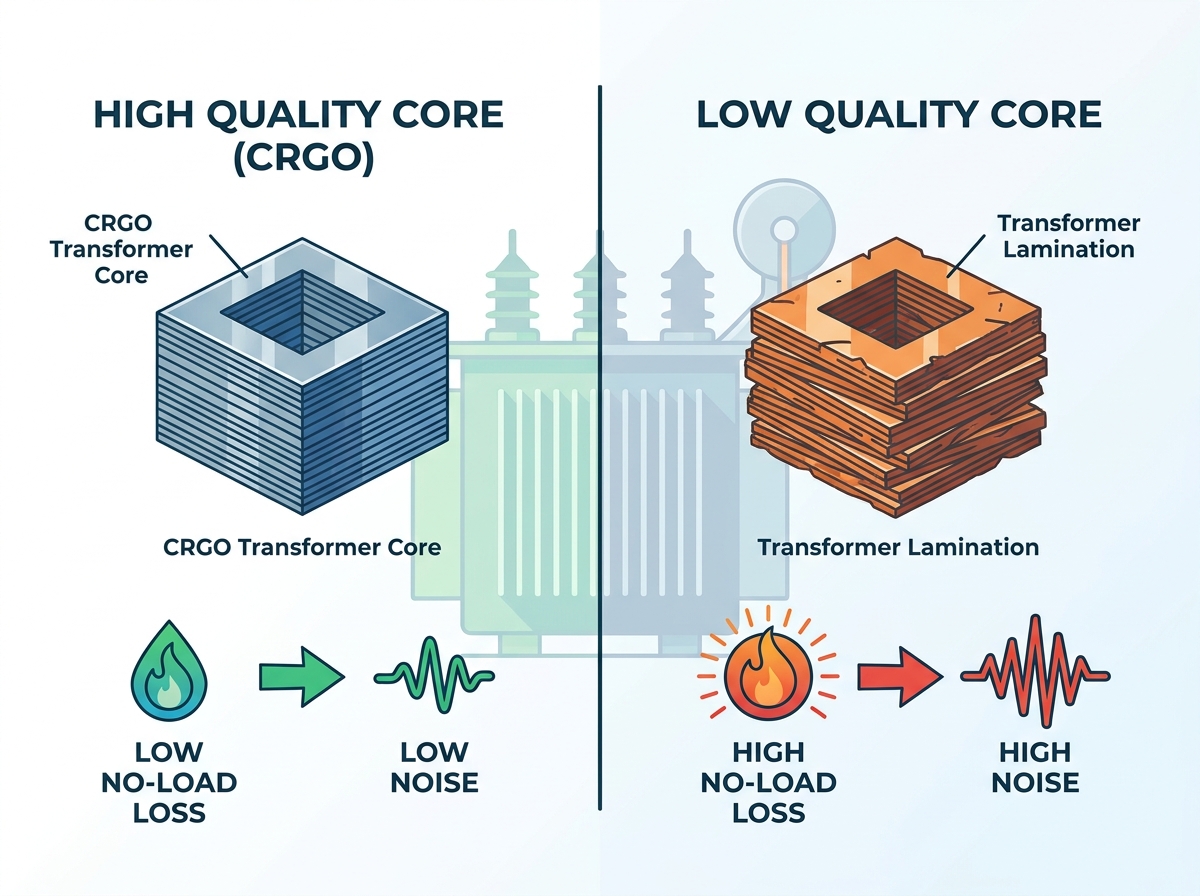
Specific manufacturing processes separate premium core construction from budget alternatives. Evaluating these variables helps you identify high-performance equipment. You cannot judge a core simply by looking at the finished transformer. You must understand the factory processes that built it.
Dull slitting tools create microscopic burrs on the edges of the steel sheets. These burrs bridge the insulation gap between laminations. This bridging creates conductive paths that exponentially increase localized eddy currents. Over time, these localized currents create dangerous hot spots that degrade the surrounding insulation. Precision cutting requires constant tool maintenance and strict quality control to keep burr heights below acceptable microscopic thresholds.
Inorganic coatings, like C5 or Carlite, protect the CRGO transformer core. Physical handling, poor tensioning during slitting, or contaminated workspaces degrade this insulation layer. Scratched or compromised coatings lead directly to interlaminar short circuits. Clean manufacturing environments are non-negotiable for core longevity. Workers must handle the steel with extreme care to prevent surface abrasions that compromise the dielectric strength between layers.
Conventional butt-lap joints offer basic performance. Modern step-lap core construction utilizes multi-step lap joints for superior efficiency. Precision step-lap joints optimize magnetic flux transition at the core corners. This smooth transition reduces localized saturation, lowers no-load loss, and minimizes excitation current. The stacking process requires immense precision. Even a millimeter of misalignment at the joints can disrupt the magnetic flux path and create localized heating zones.
Mechanical stress from slitting and cutting degrades the magnetic properties of the steel. Controlled-atmosphere annealing is necessary to restore these properties. Manufacturers subject the cut laminations to temperature profiles around 800°C. This stress relief process restores grain structure and magnetic permeability prior to final assembly. Skipping the annealing process leaves residual stresses in the metal, permanently crippling the core's magnetic efficiency and increasing operational losses.
Physical core characteristics directly impact environmental and regulatory compliance outcomes. Audible noise is a primary indicator of core mechanical health. A loud transformer is often an inefficient transformer.
Magnetostriction is the microscopic expansion and contraction of core steel under alternating magnetic fields. Lower-quality steel exacerbates this effect. High core clamping stress or higher operating flux densities also increase magnetostriction. This physical movement generates the characteristic 120 Hz or 100 Hz transformer hum. While some noise is inevitable, excessive magnetostriction points to poor material selection or aggressive design parameters pushing the steel too close to saturation.
The mechanical engineering of the core frame dictates noise propagation. Inadequate or uneven clamping pressure allows laminations to vibrate independently. This independent vibration amplifies magnetostriction noise. Premium core designs utilize epoxy bonding, core banding, and specialized dampening materials to secure the laminations and suppress resonance. The clamping structure must be rigid enough to prevent vibration but designed to avoid transferring mechanical stress directly into the magnetic steel.
Balancing technical specifications with commercial realities requires a structured framework. You must look past the initial purchase price to evaluate true operational value. A cheap transformer often becomes the most expensive asset on the grid over its lifetime.
A 10% reduction in no-load loss can offset a higher initial purchase price within the first few years of operation. Utility and industrial procurement teams use capitalization of losses, often referred to as A and B factors, to evaluate bids. These formulas assign a specific dollar value to every watt of no-load and load loss over the equipment's lifespan. By applying these factors, you can mathematically justify the investment in higher-grade core materials.
Core Material Type | Relative No-Load Loss | Initial Cost Premium | Best Application |
|---|---|---|---|
Standard CRGO | Baseline | Low | Standard distribution, low duty cycles |
Hi-B CRGO | 15% - 20% Lower | Moderate | Industrial plants, continuous operation |
Amorphous Metal | Up to 70% Lower | High | Renewable energy, high-efficiency grids |
Core quality requirements map directly to regulatory frameworks. Standards like US DOE 2016/2027 and European EcoDesign Tier 2 set strict loss limits. These standards force the transition from standard CRGO to high-permeability (Hi-B) CRGO or amorphous metal cores. Specifying compliant cores ensures you avoid regulatory penalties and future-proof your installation against tightening environmental regulations.
You must audit and verify supplier claims before taking delivery. Identifying substandard manufacturing practices early prevents costly field failures. Do not rely solely on paper specifications; verify the factory capabilities.
Inspect the cutting machinery for automated precision and tool wear monitoring systems.
Verify the presence and operational status of controlled-atmosphere annealing ovens.
Check the assembly area for strict dust, debris, and humidity control measures.
Review the manufacturer's internal quality control logs for burr height measurements.
Assess the handling procedures to ensure laminations are not bent or scratched during transit.
Mandate specific tests during the FAT process to validate performance. Do not accept generic test reports. Demand unit-specific data.
No-Load Loss Test (Open-Circuit Test): Require measurements at 100% and 110% of rated voltage to evaluate saturation performance.
Excitation Current Measurement: Verify the current draw strictly against design limits.
Sound Level Testing: Ensure testing is performed in accordance with IEEE C57.12.90 or IEC 60076-10 standards.
Interpret FAT results against guaranteed maximum loss values. Apply contractual penalties for any non-conformance to protect your investment. If a unit fails the sound or loss tests, reject it before it leaves the factory floor.
The transformer core is the heart of the asset. Compromising on core quality yields guaranteed, unrecoverable operational losses over the equipment's lifespan. Procurement teams must prioritize manufacturers who provide transparent documentation on their CRGO sourcing, cutting tolerances, and core assembly methodologies. Focus on the physical realities of the manufacturing process to ensure long-term reliability.
Audit your current transformer specifications to mandate strict burr tolerances and mandatory annealing processes.
Update your loss evaluation formulas to accurately reflect current energy costs and capitalization rates for your specific region.
Require detailed core construction data, including joint types and clamping methods, in your next equipment RFP.
Enforce rigorous FAT protocols for sound levels and excitation current before authorizing shipment to your site.
A: Core loss is dependent on the applied voltage and frequency. Because the supply voltage and frequency remain constant during normal operation, the magnetic flux in the core stays constant. Therefore, the hysteresis and eddy current losses remain steady, regardless of the load current flowing through the windings.
A: Hysteresis loss is the energy lost as heat when reversing the magnetic domains within the steel during alternating current cycles. Eddy current loss is the energy lost to localized, circulating electrical currents induced within the steel sheets by the alternating magnetic field.
A: Cold Rolled Grain Oriented (CRGO) steel aligns the grain structure of the metal. This alignment provides a path of least resistance for magnetic flux. It requires less excitation energy and exhibits significantly lower magnetostriction, which directly reduces the physical vibration that causes transformer hum.
A: Total losses include both core losses and load losses. Core losses depend on core material quality, lamination thickness, and flux density. Load losses, or copper losses, are driven by winding design, conductor material, operating temperature, and the specific load profiles of the facility.
A: External sound barriers or dampening pads can mitigate noise propagation into the surrounding environment. However, internal core noise caused by poor manufacturing, loose clamping, or inherent magnetostriction cannot be practically repaired in the field without completely rebuilding the active part.
A: Acceptable values are strictly dictated by the transformer's kVA rating, voltage class, and regional efficiency regulations. You must reference specific regulatory tables, such as DOE standards in the US or IEC EcoDesign standards in Europe, to determine the maximum allowable loss for your specific unit.
A: Burrs are sharp, microscopic metal protrusions left from cutting. They break the interlaminar insulation coating, short-circuiting adjacent steel plates. This allows eddy currents to cross between laminations, drastically increasing overall core losses and generating dangerous localized heating.


