
close
Choose Your Site
Global
Social Media


Views: 0 Author: Site Editor Publish Time: 2026-07-26 Origin: Site


Minimizing no-load losses and acoustic noise remains a persistent engineering challenge in power distribution and transmission networks. Engineers constantly seek methods to improve energy efficiency and reduce operational waste on the grid. Inefficiencies at the joint interfaces of traditional core assemblies often lead to localized heating and wasted energy. These physical bottlenecks make it increasingly difficult to meet stringent global energy efficiency regulations like DOE and EcoDesign standards. Addressing these core losses requires a fundamental shift in how we approach magnetic circuit construction on the factory floor.
Step-lap stacking introduces a definitive structural methodology for overcoming these traditional limitations. This advanced assembly technique focuses on smoothing magnetic flux transitions and significantly reducing magnetic reluctance. By staggering the joint locations across successive layers, step-lap designs maximize the inherent properties of modern electrical steels. You can achieve substantial improvements in both thermal management and acoustic performance. Implementing this architecture transforms overall efficiency and operational reliability for high-capacity grid equipment.
Step-lap joint designs significantly reduce no-load (core) losses and magnetizing currents compared to conventional butt-lap or mitred joints.
The overlapping lamination structure smooths magnetic flux transitions, directly mitigating localized heating and acoustic noise.
Maximizing the efficiency of a CRGO transformer core requires precise alignment between the step-lap geometry and the steel's grain orientation.
Automated stacking technologies are increasingly necessary to maintain the tight tolerances required for multi-step lap configurations, minimizing human error and assembly-induced stresses.
Different applications require specific structural frameworks to manage magnetic flux effectively. EI and UI laminations serve well in smaller, low-power applications where manufacturing simplicity outweighs strict efficiency demands. These basic shapes allow for rapid assembly but suffer from higher reluctance at their butt joints. In contrast, high-performance step-lap assemblies target medium-to-large power applications. They prioritize energy conservation and strict thermal management over simple assembly.
Toroidal and wound core shapes offer excellent magnetic continuity. They eliminate joints entirely along the flux path. However, winding heavy gauge wire around a large toroidal core presents significant manufacturing challenges. Stacked designs offer superior flexibility for medium-to-large power applications. Knowing when to transition from basic laminated shapes to a high-efficiency transformer core depends on your efficiency targets. Step-lap configurations become essential when regulatory compliance demands lower no-load losses.
Conventional single-step mitred joints present distinct structural limitations. Magnetic flux naturally crowds at these sharp intersections. This crowding creates high reluctance gaps and forces the flux to cross perpendicular to the steel's grain orientation. As a result, localized heating increases, and overall efficiency drops. Single-step joints also require higher magnetizing currents to push the flux across these physical barriers.
Step-lap geometry solves these structural bottlenecks by staggering the joint locations. Engineers offset the cuts across successive layers of transformer lamination. This staggering creates a continuous, low-reluctance path for the magnetic field. The flux easily bridges the small air gaps by transferring to the adjacent overlapping layer. This smooth transition minimizes flux crowding and drastically reduces energy waste.
Basic step-lap designs improve performance, but multi-step lap configurations push efficiency further. Manufacturers typically progress from a simple 2-step design to complex 3-step, 5-step, or even 7-step patterns. Each additional step further staggers the joint locations along the core leg. This progression requires highly precise cutting and stacking equipment.
3-Step Lap: Provides a baseline improvement over single mitred joints, distributing the gap across three distinct layers.
5-Step Lap: The industry standard for medium power distribution, offering an optimal balance between manufacturing complexity and loss reduction.
7-Step Lap: Reserved for large power transformers where maximum efficiency and noise reduction justify the extreme precision required.
Increasing the number of steps distributes the air gap over a much larger surface area. This distribution prevents localized flux density spikes at any single joint. The magnetic field experiences a smoother transition zone. Consequently, the core requires less energy to maintain the magnetic circuit. Multi-step configurations represent the industry standard for high-efficiency power distribution equipment.
Optimizing step widths involves precise engineering principles to prevent magnetic saturation. If the overlap zone is too narrow, the flux density exceeds the material's saturation point. This saturation leads to rapid heating and energy loss. Engineers calculate the exact step width required to maintain optimal flux density across the transition zone.
Varying step width geometries directly influences magnetic flux distribution. Proper optimization minimizes the excitation power required to magnetize the core. Mathematical modeling helps determine the ideal balance between step width and material utilization. This precision ensures the core operates within its most efficient magnetic parameters.
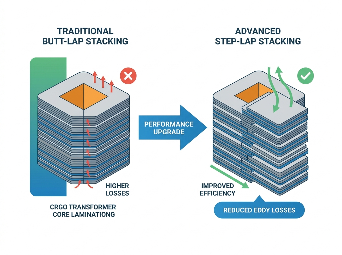
Understanding the physics of flux transition across overlapping joints reveals the true value of step-lap designs. Magnetic reluctance drops significantly when flux can bypass air gaps through adjacent steel layers. This bypass mechanism directly reduces hysteresis losses. The magnetic domains align more easily, requiring less energy during each alternating current cycle.
Transitioning to a step-lap design yields measurable reductions in eddy current losses. The staggered joints prevent large circulating currents from forming at the corners. This efficiency directly impacts the overall magnetizing current. You will observe a lower current draw required to establish and maintain the magnetic field.
Performance Metric | Conventional Mitred Joint | Multi-Step Lap Joint |
|---|---|---|
No-Load Losses | Baseline | Reduced by 10% to 15% |
Acoustic Noise | Higher decibel output | Reduced by 3 to 5 dB |
Magnetizing Current | Higher requirement | Significantly lower |
Localized Heating | Prone to corner hot spots | Uniform temperature distribution |
Magnetostriction causes the steel laminations to expand and contract during magnetization. This microscopic movement generates audible noise. Joint gaps in conventional cores amplify these vibrations. The resulting hum can be problematic, especially in urban environments.
Step-lap cores provide superior mechanical stability. The distributed gaps and overlapping layers dampen vibration frequencies effectively. This structural integrity restricts the physical movement of the laminations. Lowering audible noise is a strict requirement for indoor substation deployments and residential area installations.
Smoothing the flux path prevents localized flux saturation at the corners. Conventional joints often create hot spots due to flux crowding. These hot spots degrade insulation over time and reduce equipment lifespan. Step-lap designs ensure a uniform flux distribution.
Eliminating hot spots provides significant downstream benefits for cooling requirements. You can often reduce the size of radiators or cooling fans. Consistent thermal management protects the dielectric paper and oil. This protection ensures long-term insulation longevity and operational safety.
Cold Rolled Grain Oriented steel is the absolute prerequisite for step-lap designs. The manufacturing process aligns the crystalline structure of the steel in the rolling direction. This alignment creates a path of least resistance for magnetic flux. Using non-oriented steel would negate the benefits of the staggered joint architecture.
Engineers design the step-lap cut angles to keep the magnetic flux aligned with this rolling direction. Typically cut at 45 degrees, these joints ensure the flux rarely travels cross-grain. A well-designed CRGO transformer core maximizes the material's inherent magnetic permeability. This synergy between material and geometry drives modern efficiency standards.
Manufacturers utilize ultra-thin silicon-doped steel sheets in step-lap assemblies. Thicknesses typically range from 0.23mm to 0.27mm. Silicon doping reduces the bulk electrical conductivity of the steel. Lower conductivity restricts the flow of eddy currents within the individual sheets.
This material property works in tandem with the step-lap joints to suppress localized losses. However, a distinct manufacturing trade-off exists. Thinner laminations reduce losses but significantly increase the required number of layers. This increase adds to assembly complexity and processing time.
CNC slitting and cutting precision are critical for step-lap success. Misaligned step widths completely negate the magnetic benefits of the design. If the overlaps do not align perfectly, air gaps increase, and reluctance spikes. Strict quality control during the cutting phase is non-negotiable.
Nesting and optimization algorithms maximize raw CRGO steel usage. These algorithms reduce material waste during the cutting process. Additionally, manufacturers must control burr formation. Burrs can puncture the thin insulating coating on the steel, causing interlaminar short circuits and massive localized heating.
The industry is rapidly shifting toward advanced automated stacking systems. E-stackers provide a significant technical advantage. These systems cut and stack the core steel into its final position in a single, continuous process. Automation ensures perfect alignment of the complex multi-step geometries.
Minimizing physical handling eliminates manual assembly error. Human handling often introduces mechanical stress to the fragile CRGO sheets. Bending or dropping the steel degrades its magnetic properties. Automated systems protect the material integrity from coil to final core assembly.
Multi-step lap cores require higher initial manufacturing and tooling costs. The specialized CNC equipment and automated stackers represent significant capital investments. Complex cutting programs also require skilled operators and engineers.
However, you must calculate returns based on lifetime energy savings. Reduced cooling costs and compliance with efficiency mandates quickly offset the initial investment. Lower no-load losses translate directly to continuous operational savings over the equipment's 30-year lifespan.
Define strict baseline requirements before specifying a core design. Establish target no-load loss limits based on regulatory requirements. Determine maximum allowable decibel ratings for the installation site. Consider footprint constraints, as highly efficient cores may allow for smaller overall tank designs.
Establish clear criteria for vetting core manufacturers. Demand proof of quality control regarding step widths and cutting tolerances. Prioritize suppliers with automated stacking capabilities. Verify their ability to handle thin-gauge CRGO materials without introducing mechanical stress.
Map step-lap performance capabilities directly against Tier 2 EcoDesign and DOE standards. These regulations dictate strict maximum loss levels. Step-lap architecture is often the only viable path to compliance without drastically oversizing the core.
Assess scalability across your equipment portfolio. Step-lap designs scale effectively from small distribution units up to large power transformers. The fundamental physics remain consistent, ensuring reliable performance gains across all capacity ratings.
Initiate a pilot evaluation of a multi-step lap prototype for your next high-efficiency project.
Request specific core loss testing data, such as Epstein frame test results, from potential suppliers.
Audit supplier facilities to verify the presence of automated E-stacking and strict burr-control processes.
Update procurement specifications to mandate step-lap construction for all units requiring low acoustic noise profiles.
A: The primary advantage is the significant reduction of no-load losses and lower acoustic noise. By smoothing magnetic flux transitions across lamination joints, it minimizes magnetic reluctance. This design also improves steel usage efficiency and reduces localized heating at the core corners.
A: A multi-step lap distributes air gaps across 3 to 7 staggered layers, whereas a single-step lap uses only one offset. This wider distribution further minimizes magnetic reluctance, prevents flux crowding, and provides a much smoother transition path for the magnetic field.
A: Step-lap geometry relies entirely on the directional magnetic properties of Cold Rolled Grain Oriented steel. The staggered joints are cut at specific angles to keep the magnetic flux aligned with the steel's rolling direction, maximizing magnetic permeability and overall efficiency.
A: Yes, step-lap stacking significantly reduces transformer noise. The overlapping joints provide superior mechanical stability, which restricts the physical movement of laminations caused by magnetostriction. This dampens vibrations and lowers the audible decibel levels during operation.
A: The main challenges include the need for extreme precision in CNC cutting and step width optimization. Misaligned cuts negate the magnetic benefits. Additionally, automated inline stacking is necessary to prevent material stress and human error during the complex assembly process.
A: Step-lap construction lowers the overall magnetizing current required. Because the staggered joints create a path of lower magnetic reluctance, the core requires less electrical energy to establish and maintain its magnetic field compared to conventional mitred joints.


